
Enabling RoCEv2 in Enterprise SONiC
RDMA over Converged Ethernet (RoCE) provides Remote Direct Memory Access (RDMA) over an Ethernet network, enabling memory transfer between two devices that bypasses the CPU on each device. This is a capability that is configurable in Enterprise SONiC. We at BE Networks have worked closely with our partners to bring this capability into Verity, to simplify fabric-wide configuration of SONiC on their hardware platforms.
Verity 6.3 (current GA version) supports configuring RoCE in SONiC. Verity uses Device Setting Templates to enable this feature on a per switch basis. This guide will detail the steps to create the template, apply it to the switch, and then verify the configuration on the switch.
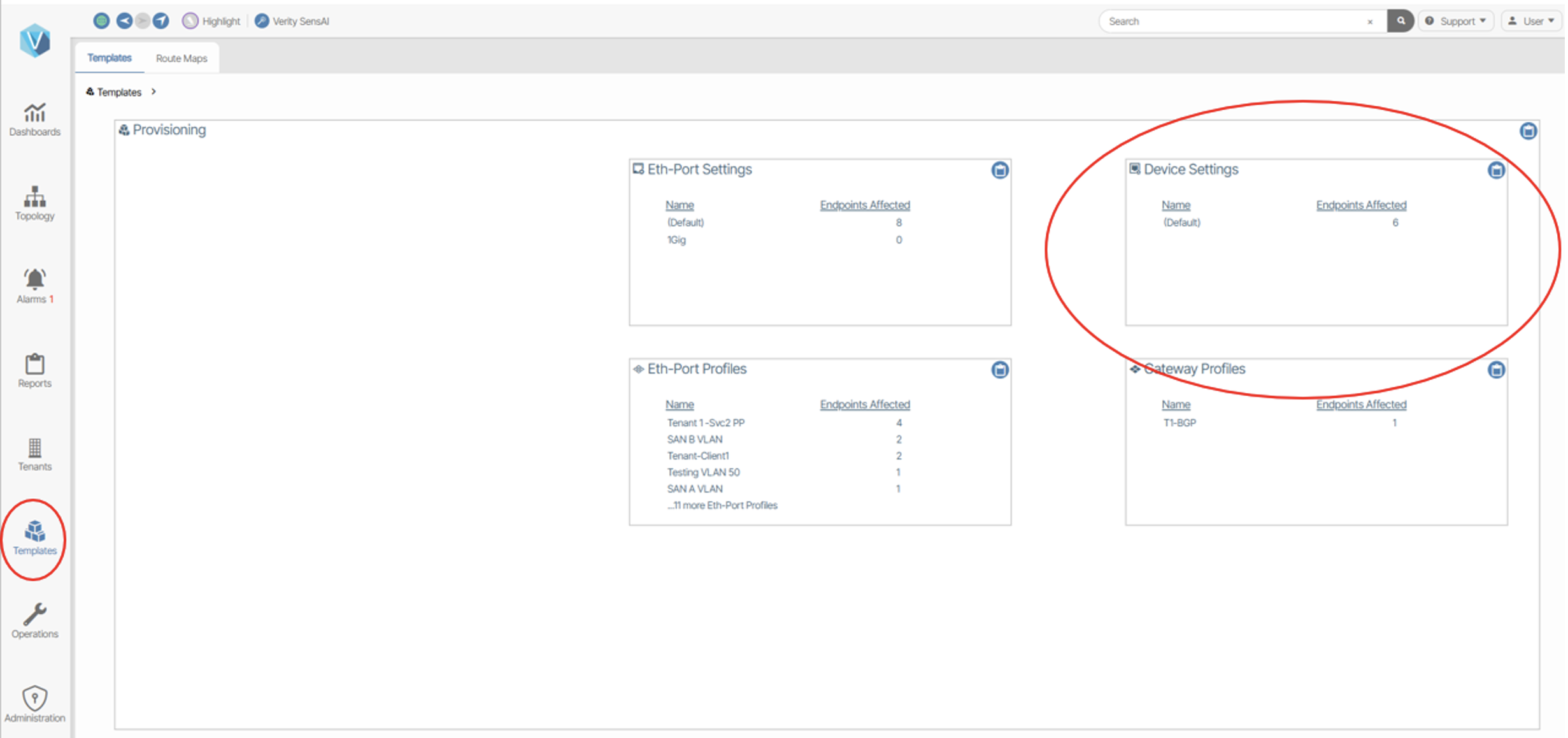
Figure 1
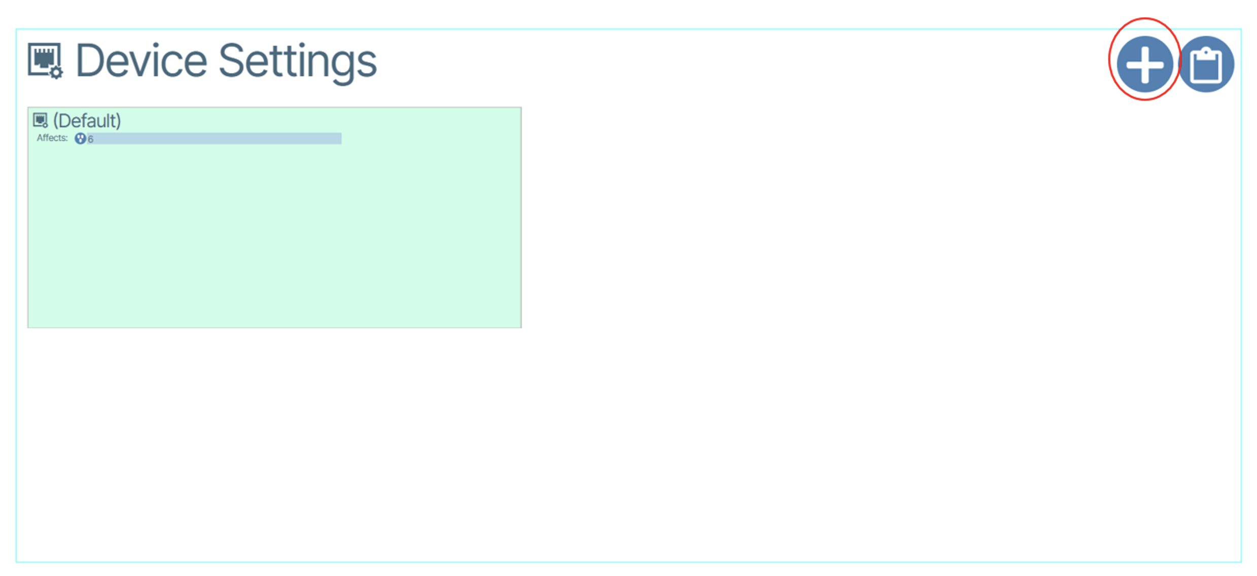
Figure 2
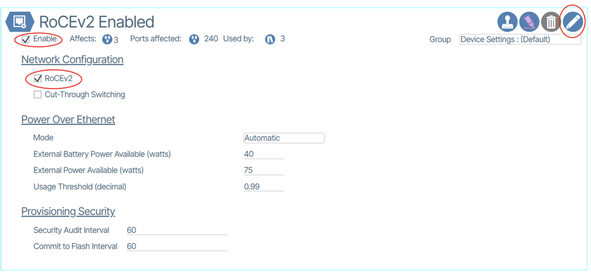
Figure 3
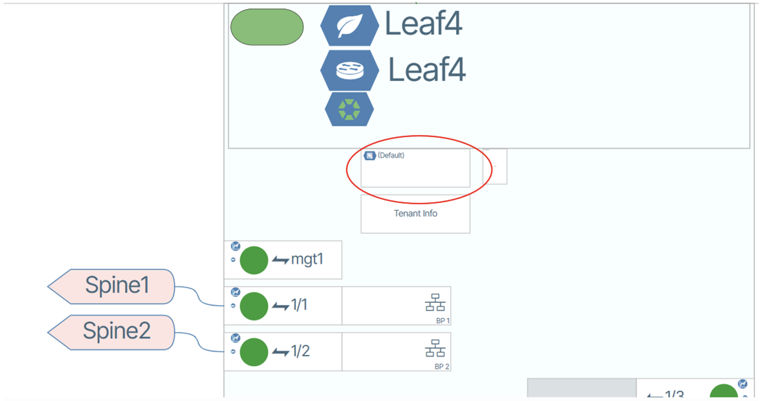
Figure 4
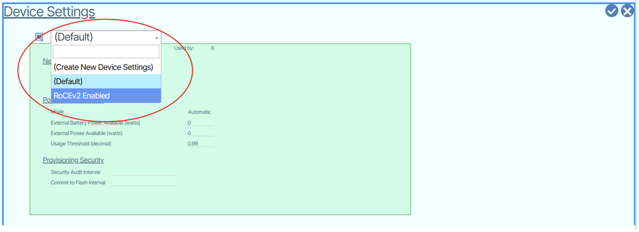
Figure 5

Figure 6
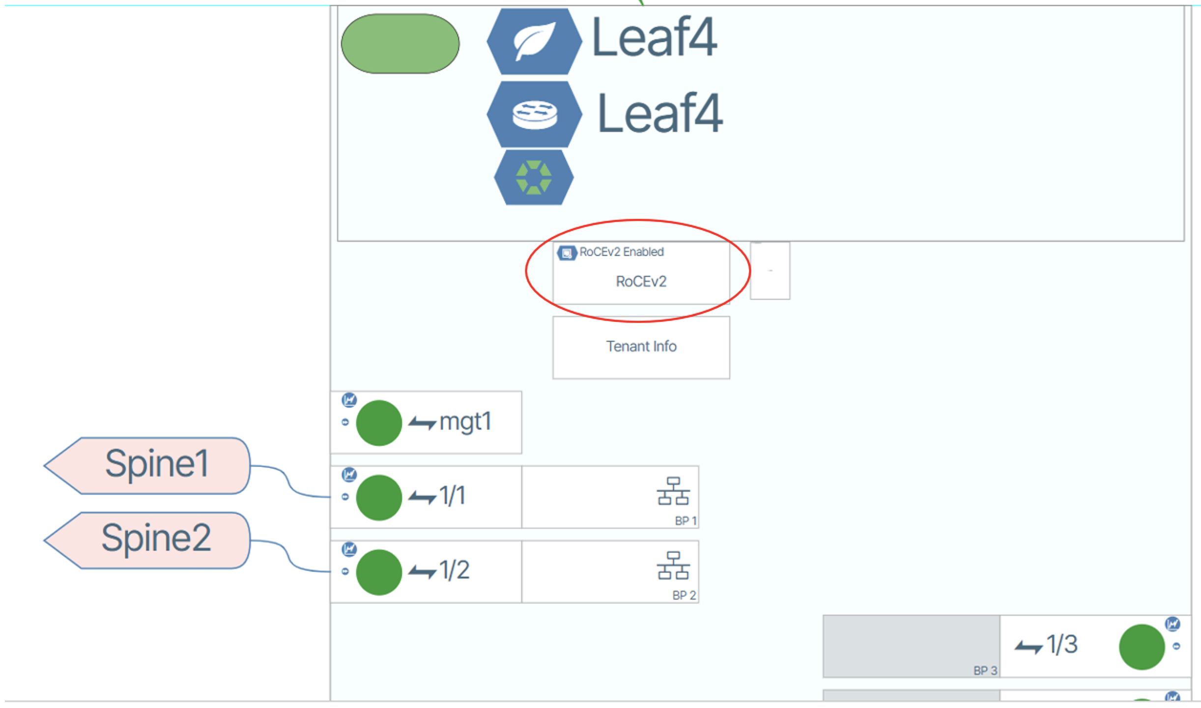
Figure 7
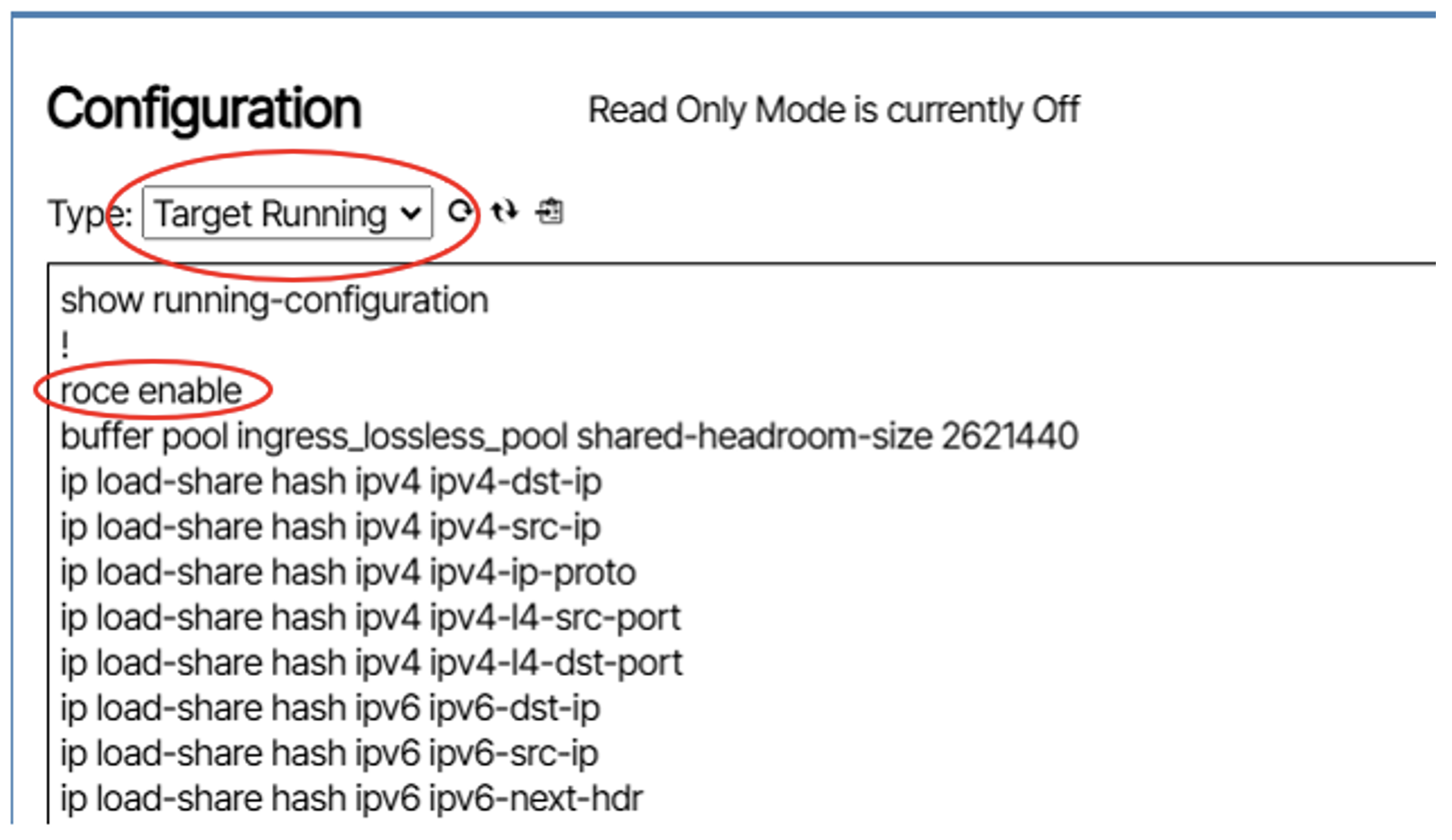
Figure 8
Next, if you scroll down to the QoS settings, you will see the configured RoCE QoS settings:
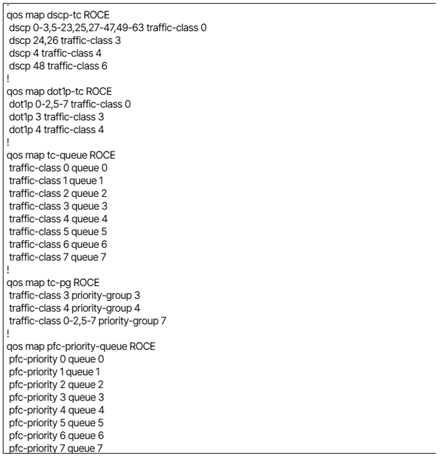
Figure 9

Figure 10
You can apply this Device Settings template to any switches that need to have RoCE enabled.
In a future blog post, we will cover how to manually configure these settings to fine tune RoCE traffic. This functionality is due in a near-term release of Verity.
RoCE is currently limited to Trident 3×7, Trident 4×11, Tomahawk 3, Tomahawk 4 and Tomahawk 5 chips sets.
- Enabling RoCE requires the switch to reboot after configuration is applied.
- Breakout ports must be configured BEFORE enabling RoCE.
- Tuning RoCE parameters is a future capability in Verity and is not supported in the current release.
- RoCE is required to be enabled on all devices that will be in the path of RoCE traffic.
- Servers need to be configured to use RoCE.

Luke Williams
Product Lead
With over 30 years experience in the IT field, there is not a whole lot Lucas hasn’t seen. From running a local ISP in his home town in Iowa when he was 16 to managing networks and server administration at the second largest newspaper media company in the United States in 2012, to developing IoT solutions and Networking NOS's while working at Canonical, he is constantly learning and trying new technologies to keep up with markets and company demands for new technologies to meet their needs. He currently is the Product Lead at BeyondEdge Networks specializing in Open Networking and SONiC.


